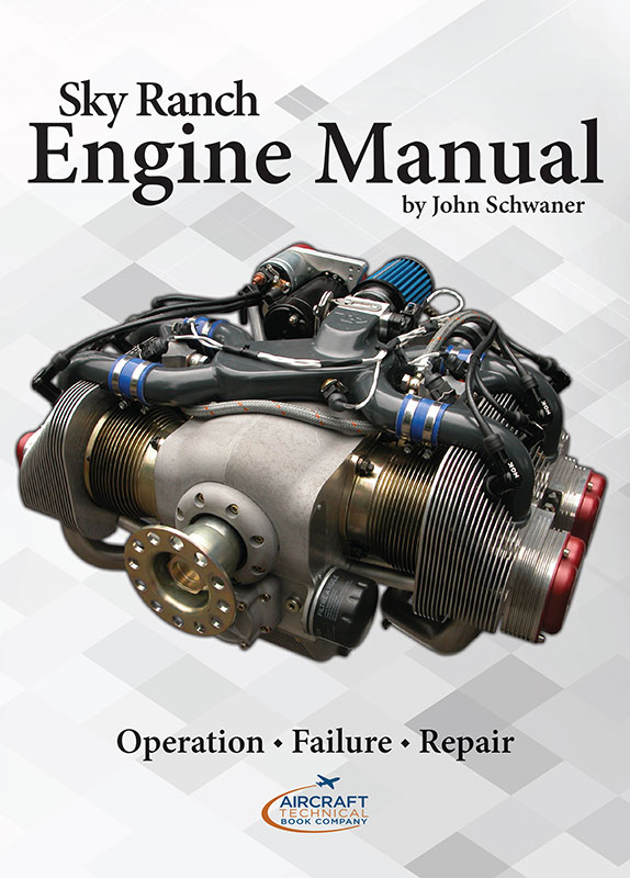
John Schwaner, proprietor of Sacramento Sky Ranch, authors one of the most definitive manuals on aircraft engine maintenance we’ve ever seen. He explains the piston aircraft engine with a practical day to day approach, but directed towards the operator and repair personnel.
His comprehensive book takes you from the fundamentals of how an aircraft engine works to the arcane art of engine diagnostics. In between, John takes the time to give the reader a detailed explanation of how each component of a modern aircraft engine affects performance.
Sky Ranch Engine Manual thoroughly covers the operation, inspection and maintenance of the Lycoming and Continental piston aircraft engine, including a very comprehensive troubleshooting guide. This book goes beyond the basic theory of aircraft reciprocating engines, but instead focuses on the practical aspects for mechanics and operators of why things go bad, how to repair them, and most important; how to keep them from failing in the first place.
He covers factors such as lubrication and wear, electrical issues, mechanical alignment, heat related problems, vibration and balance, etc. The chapter on troubleshooting alone is worth it’s weight in gold. Highly recommended.
The chapter on troubleshooting alone is worth it’s weight in gold. Highly recommended.
Excerpts from the Sky Ranch Engineering Manual
Fatigue Analysis
Regardless of the claims of marketing departments, you can zero-time a logbook but you can not zero-time the metallurgy. Engine parts have a wear life and they have a fatigue life. The primary reason components fail catastrophically in service is due to metal fatigue. With a knowledge of fatigue you will see the reason behind many maintenance practices and recommendations. The design engineer can design for metal fatigue, but it is up to the mechanic or operator to inspect for metal fatigue.
Fatigue fractures are the most serious and most common types of failure in machinery. Fatigue fractures can occur under normal operating conditions without excessive overloads. The Comet I aircraft failures in the early 1950s were the result of low-cycle fatigue caused by repeated cabin pressurizations. These are the earliest examples of catastrophic structural failure occurring on airplanes that have not been stressed beyond their limits. Other fatigue failures include the 1988 Boeing 737-200 fuselage failure on Aloha flight 243, and the F-111 wing that failed in 1968 after a few hundred hours (the estimated life was 4,000 hours). These failures demonstrate that because of metal fatigue, a safe load applied once becomes unsafe when applied many times.
More common types of fatigue failures include exhaust valve breakage in older 80-octane Lycoming engines, spalling of camshaft followers, failure of propeller blades in unlimited aerobatic airplanes, and failure of the crankshaft flange on Lycoming "lightening hole" crankshaft's. Most of us use fatigue when we break off a piece of metal wire by repeated bending. The wire breaks because of a low-cycle fatigue fracture.
Fatigue failures are always brittle failures which occur without buckling. A wing or engine mount should buckle rather than snap. With the pursuit of lightweight vehicles, the advent of new lightweight designs and computer stress analysis, it is possible to create structures which are of minimum weight. As a result, more high-strength steels are used under high stress conditions. Unfortunately, increasing the hardness of steel decreases its ductility and it becomes more subject to brittle fatigue failure under service stress conditions. High strength, high stress and low ductility create catastrophic fatigue failure modes. As a consequence, the engineer must predict the fatigue life of the component and the component must be inspected for fatigue or removed from service.
Any time that we inspect a structure for cracks, a knowledge of stress and fatigue enhances our ability to examine that part. To pursue our understanding of metal fatigue, we will investigate some properties of materials...
Analysis of Engine Contaminants
Imagine you have just purchased that dream airplane. During the purchase, you did everything right. You had the airplane checked out, including a pre-purchase inspection. The engine was examined and an oil analysis sample was taken with normal engine wear reported by the lab. The airplane is in perfect condition.
Six months later, your shop tells you that the engine is contaminated with metal, the camshaft is shot, and the engine has to be disassembled. The cost of repair is no less than $3,000 and probably more.
Unfortunately, once or twice a year, I see one of these engines. What is more unfortunate in some cases is that the engine had already failed before the purchase; the normal pre-purchase inspections had failed to detect the failure.
An engine can operate normally, pass compression tests and oil analysis, and still have damage to the camshaft lobe and follower. Even when a camshaft lobe has ground down to 1/2 its original shape, the only indication is that the engine fails to produce rated power. Engines with a fixed-pitch propeller may not produce rated RPM. But on engines with a constant-speed propeller, lack of engine power may not be noticeable. Engine roughness occurs only when the camshaft lobe has been totally wiped out.
There is one specific type of inspection that detects this type of occurrence in the early stage without disassembling the engine: a thorough oil filter examination.
Proper inspection of the oil filter is the best method of detecting camshaft or cam follower spalling and failure. Cut the oil filter open and wash and rinse the filter media carefully into a bucket of clean solvent. The washing shifts particles into the bucket. Using a clean magnet, work it around in the solvent solution. Ferrous metal particles in the solution will adhere to the magnet, allowing inspection. A visual inspection of the cam followers is warranted if the end of the magnet is covered with metal slivers.
You will not detect early signs of cam follower damage by taking the filter media out of the can and spreading it out on a table. There is not enough metal at this stage of failure to be visible in the folds of the filter. Oil pressure forces the small slivers of metal into the filter media where they are not visible. A magnet concentrates the small amount of metal, making it visible. Unless the examination of the oil filter is done correctly, you will not get a reliable analysis.
Engine Operation - Descent
Make the initial temperature change slowly. We want to start the temperatures going down early. Once you establish the downward trend in temperatures, there is far less likelihood of causing engine damage by fast cooling.
There are three ways in which you are going to cool the engine:
- Reduction of power.
- Increase in airspeed.
- Enrichening the mixture.
The worst thing you can do is to do all three of them at once. Start the initial cooling trend by lowering the nose by keeping the power and mixture the same. Try to make small changes in RPM and manifold pressure. Limit yourself to 1 or 2 inches of manifold pressure reduction at a time. To prevent rapid turbocharger cool down during descent, the desired EGT is 1350F.
Every flight, you should anticipate a rapid descent and start a cool-down before the let-down. Reduce power or open the cowl flaps part way to start reducing the temperature of the engine. When you have to do the fast descent, you can close the cowl flaps and be less concerned since you have already reduced engine temperatures.
You do not want to do a long let-down with the prop driving the engine. This causes ring flutter and broken piston rings. High RPM's increase the up-and-down inertia load on the rings in the piston grooves. Cylinder pressures help to keep the rings seated to the bottom of the ring groove. Reducing RPM to low cruise will be beneficial by reducing ring inertia and increasing cylinder pressures. Of course, at some time (as on final) the prop will be driving the engine and this is okay for a short time. But a long descent at high RPM and low manifold pressure is hard on the piston rings.
Prolonged engine idle during glide, particularly in cold weather conditions with a carbureted engine, may result in engine stoppage. The primary cause of this type of engine stoppage is the inability of the engine to receive adequate fuel/air mixture ratios. During idling flight, propeller wind-milling induces an engine RPM that is higher than the ground idle RPM for which the mixture adjustment of the carburetor was set. This produces a lean fuel/air mixture ratio. When the throttle is opened rapidly, the fuel delivery by the carburetor lags behind the throttle motion due to surface tension and inertia in the fuel, and this further leans the available mixture. The cylinders have inadequate fuel and the engine misfires or quits.
TABLE OF CONTENTS
- Introduction
- How your engines works
- Continental engine specifications
- Lycoming engine specifications
- Chapter 1 Fatigue Analysis
- Stress and strain
- Fatigue
- Stress flow
- Stress risers
- Surface finish
- Residual stress
- Compressive residual stress
- Autofrettage
- Shot peening
- Nitriding
- Rolled threads
- Tensile residual stress
- Plating
- Bending
- Grinding
- Cold working
- Stress relieving and annealing
- Contact fatigue
- Fretting fatigue
- Cracks and fractures
- Fatigue cracks
- Thermal fatigue fracture
- Unexpected sources of fatigue damage
- Field analysis of fatigue failure
- Torsional failures
- Chapter 2 Engine Inspection
- Oil starvation
- Prop strikes
- Stuck valves
- Engine parts
- Engine contaminants
- Camshaft follower failure modes
- Oil analysis
- Oil filter analysis
- Dirt, silica and silicone
- Metal particles - identification
- Inspection of contaminated aircraft oil systems and oil coolers
- Crankcase fretting in Continental engines
- Flow porting and its effect on cylinder head cracks
- Chapter 3 Engine Performance
- Starting and idle
- Take-off
- Climb
- Cruise
- Leaning
- Descent
- Taxing and shutdown
- Chapter 4 Cylinder Repairs
- How engine angle head rocker arm alignment
- Intake guide seals
- Cylinder honing
- Cylinder choke and piston design
- Chrome plate piston ring failures
- Do the rings rotate?
- Piston inspection
- Connecting rod line boring
- Color coding of cylinders
- Chapter 5 Lubricants & Wear
- The function of engine oils
- Cylinder Barrel Wear - Steel Barrel Cylinders
- Cylinder Barrel Wear - Chrome Cylinder Barrels
- Intercooling Effects on cylinder wear
- Greases
- Friction Laws applied to hydrodynamic lubricated surfaces
- Friction Laws as applied to boundary lubrication
- Oil additive supplements
- Chapter 6 Hose Assemblies
- Age Limit on hoses
- Condition Limit on hoses
- Buna-N rubber and toluene
- Firesleeve those hoses
- The hose mandrel
- Classification of hose defects
- Chapter 7 Fasteners and Failures
- What is a bolt?
- Stress distribution within the bolt
- Stress distribution within the nut
- Equalizing stress distribution
- Paint and broken cylinder studs
- Torque accuracy
- Connecting rods
- Chapter 8 Calibration
- What needs to be calibrated
- What does not need to be calibrated
- Calibration interval
- Calibration Reports
- Chapter 9 Troubleshooting
- Sixty engine symptoms diagnosed
- Chapter 10 Performance Limits
- Fits and Limits
- Displacement
- Horsepower
- BMEP
- Propeller Load Curve
- Power Curve Construction
- Chapter 11 Forces, Vibrations, Balance
- Rotating Balance - rotational motion
- Reciprocating Balance - translational motion
- Reciprocating Force Analysis
- Torsional Balance
- Balancing the oil film
- Torsional Effects
- Connecting rod balance
- Vibration Isolation
- Gyroscopic couples
- Chapter 12 Lycoming Engine Specifications
- Chapter 13 Lycoming Connecting Rods
- Chapter 14 Glossary

.jpg)